
Understanding the symbols and conventions in blueprints and plans is key to interpreting design details accurately. These standardized symbols communicate important information about doors, windows, electrical outlets, plumbing, and structural elements. Using legends, scales, and recognized patterns helps you translate abstract drawings into real-world construction steps. Mastering these conventions guarantees clear communication and reduces errors. If you keep exploring, you’ll uncover more ways to confidently interpret plans and contribute effectively to projects.
Key Takeaways
- Legends decode symbols, line types, and abbreviations to accurately interpret construction plans.
- Recognizing standardized symbols ensures consistent understanding of doors, windows, electrical, and plumbing fixtures.
- Scale measurements translate plan dimensions to real-world sizes, aiding precise construction and material estimation.
- Conventions and symbols follow industry standards, facilitating quick interpretation and reducing errors across plans.
- Mastering these visual cues enhances communication, accuracy, and efficiency during project execution.
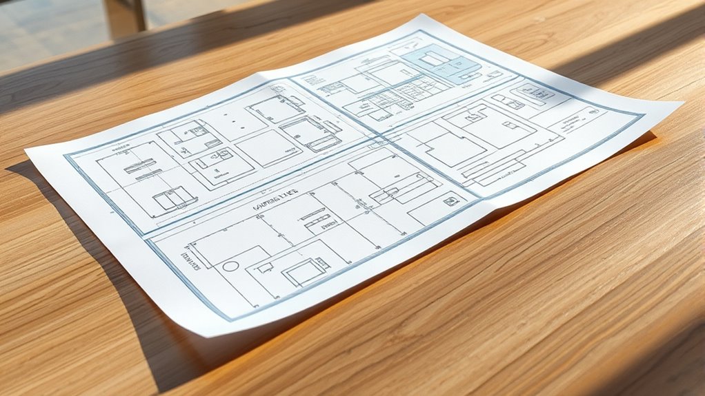
Have you ever wondered how builders turn a simple idea into a finished structure? It all begins with reading the plans and blueprints that serve as the blueprint for construction. These detailed drawings communicate every aspect of a project, but they rely heavily on symbols, conventions, and measurements to do so effectively. When you start learning to interpret these plans, understanding legend interpretation becomes essential. The legend acts as a key, translating symbols, line types, and abbreviations into meaningful information. Without a clear legend, the symbols on the blueprint are just shapes and lines, making it hard to grasp what each one represents. You need to familiarize yourself with these legends to decode the symbols for doors, windows, electrical outlets, plumbing, and structural elements. This process allows you to visualize the design accurately and guarantees everyone involved in the project is on the same page.
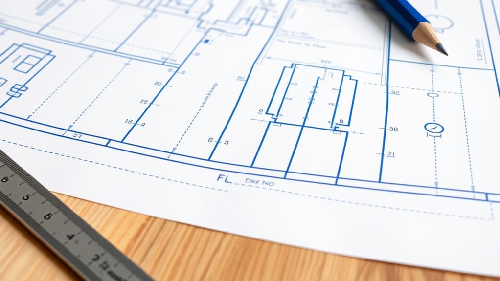
Scale measurement is another critical aspect of reading blueprints. Builders use scale to represent large structures on smaller sheets of paper, making detailed drawings manageable and easy to read. For instance, a common scale might be 1/4 inch equals 1 foot, meaning every quarter-inch on the drawing corresponds to one real foot of the building. When you understand the scale measurement, you can accurately translate dimensions from the plan to actual construction. This skill helps prevent costly mistakes and guarantees that parts fit together as intended. You’ll also learn how to measure distances directly on the blueprint using a scale ruler, which is specially marked for different scales. By doing so, you can verify dimensions, estimate material requirements, and coordinate various trades more efficiently.
As you become more familiar with reading plans, you’ll notice that symbols and conventions follow standardized rules, which makes the interpretation process more straightforward across different projects. Recognizing these patterns allows you to quickly identify key features and understand their placement and relationships within the design. Whether you’re reviewing a blueprint for framing, electrical wiring, or plumbing, knowing how to interpret legends and measurements saves time and reduces errors. It’s like learning a language—once you understand the symbols and their meanings, communicating ideas and instructions becomes much clearer. In essence, mastering legend interpretation and scale measurement transforms a complex set of drawings into a practical guide, giving you the confidence to contribute effectively to any construction project.

The Reading Comprehension Blueprint Activity Book: A Practice & Planning Guide for Teachers
As an affiliate, we earn on qualifying purchases.
As an affiliate, we earn on qualifying purchases.
Frequently Asked Questions
How Do I Interpret Symbols for Electrical Systems?
To interpret symbols for electrical systems, you should first familiarize yourself with common circuit symbols for electrical wiring components like switches, outlets, and lights. Look at the blueprint’s legend or key to match symbols with their functions. When you see a particular symbol, visualize the electrical wiring path it represents. This helps you understand how the circuit is connected and operates, ensuring accurate installation or troubleshooting.
What Are Common Blueprint Abbreviations I Should Know?
You should know common construction abbreviations like ‘CL’ for centerline, ‘EL’ for elevation, and ‘TYP’ for typical. These blueprint symbols streamline communication, making plans clearer. Recognize abbreviations such as ‘R’ for radius, ‘Ø’ for diameter, and ‘CF’ for cubic feet. Familiarizing yourself with these construction abbreviations assists you quickly interpret drawings and ensures accurate understanding of the blueprint details.
How Do Line Types Indicate Different Materials?
Line types on blueprints help you identify different materials clearly. Solid lines usually indicate structural elements like concrete or steel, while dashed or hidden lines show features behind surfaces or concealed materials. Different line types, such as dotted or chain lines, distinguish between materials like insulation, piping, or electrical conduits. Recognizing these line type distinctions allows you to accurately interpret material identification and understand the construction details effectively.
What Scale Is Typically Used in Residential Blueprints?
You’re on the right track when you ask about residential blueprints; the typical scale used is 1/4 inch equals 1 foot. This scale notation helps you easily translate blueprint measurements into real-world dimensions. Keep in mind, a good rule of thumb is to double-check the scale on the drawing to make certain of accuracy. This way, you won’t be caught off guard when turning those measurements into actual construction details.
How Can I Identify Load-Bearing Walls in a Plan?
You can identify load-bearing walls by checking foundation details and wall framing methods on the plan. Load-bearing walls are usually thicker or marked with specific symbols, indicating their importance. They often align with foundation elements, supporting the structure above. Look for notes or symbols that highlight these walls, and compare them with non-structural partition walls. This helps you determine which walls carry the load and are essential for stability.

Rena Chris Architectural Scale Ruler: 12" Imperial Aluminum Alloy Metal Architecture Measuring Tools, Engineering Drafting Construction Drawing Blueprints Triangular Architect Scaling Rulers 12 Inches
12" triangular architect scale designed to facilitate the drafting and measuring of architectural drawings, such as floor plans,…
As an affiliate, we earn on qualifying purchases.
As an affiliate, we earn on qualifying purchases.
Conclusion
Now that you understand the symbols and conventions, you’re ready to dive deeper into blueprints. But remember, every plan holds secrets waiting to be uncovered—you just need to know where to look. As you navigate through complex designs, stay alert for hidden details that could change everything. The more you learn, the more intriguing the world of plans becomes. Are you prepared to reveal its mysteries and see what lies beneath the surface?

Commercial Electrical Construction Drawings: A Comprehensive Guide: Understanding Symbols, Schedules, and Systems for Professionals
As an affiliate, we earn on qualifying purchases.
As an affiliate, we earn on qualifying purchases.

Legend Planner Hourly Schedule Edition – Deluxe Weekly & Daily Organizer with Time Slots. Time Management Appointment Book Journal for Work & Personal Life, Undated, A5 Hardcover – Viridian Green
CREATE THE LIFE YOU'VE ALWAYS WANTED – This Legend Planner undated hourly planner 2025-2026 will help you figure…
As an affiliate, we earn on qualifying purchases.
As an affiliate, we earn on qualifying purchases.